
(Completed: 2010)
Abstract
In an investigation involving a loss at a chocolate manufacturing facility, wherein a leak occurred in a section of process piping that allowed water to contaminate the chocolate, Augspurger Komm Engineering (AKE) expert, Mark Cannon conducted inspections at the facility and of the pipe section where the leak occurred.
Overview
Subject Unit Summary
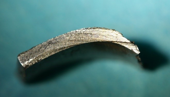
The subject pipe section is part of a larger installation at the facility, which was fabricated and installed by a third-party vendor. The piping was in service for almost two years and was subjected to flowing hot water, which contained various types of chemicals used for treating the water system of the plant. The subject component became operational in April 2007. The source was isolated to a section of piping that was removed and sent to a laboratory for inspection, and AKE became involved in the investigation. The pipe section removed for analysis is shown in Figure 1.
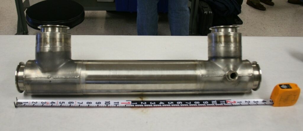
Figure 1 – Pipe section assembled by pipe vendor and removed from chocolate facility
The Investigation & Findings
The pipe section was comprised of off-the-shelf components such as flanges, elbows, tees and threaded couplings, which the pipe company purchased, modified in accordance with specifications provided by the chocolate facility, then assembled. The purpose of the assembly is to surround liquid chocolate with hot water to keep it viscous enough to pump through the facility.
As shown in Figure 2, hot water as indicated by the blue arrow, flows into the small port on the side of the assembly and flows out of a matching port on the opposite end. The chocolate, as indicated by the brown arrow, flows through the central section of the pipe. The hot water thus creates a heated jacket around the chocolate through co-annular flow.
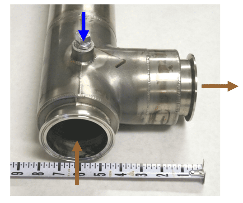
Figure 2 – Pipe section showing flow of water (blue arrow) and chocolate (brown arrow)
In addition, the vendor voluntarily tested each section for leaks with compressed air at 80 psi. The operating pressure of the hot water side of the pipe system was 20 psi.
Laboratory Inspection
A visual inspection was performed on the pipe section and it was pressurized with air and immersed in a water tank to look for bubbles coming from the leak, which was finally located on an inside radius of one of the tees. (Figures 3 and 4)
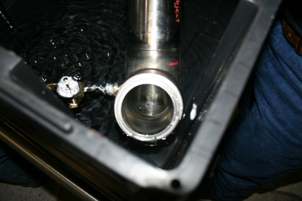
Figure 3 – Pipe section pressurized and immersed created bubbles from leak
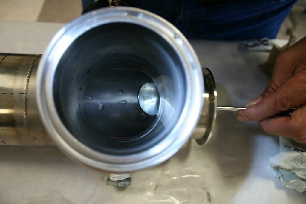
Figure 4 – Leak located on inside radius is reflected in the mirror
This tee component had been purchased from a plumbing parts manufacturer, without any modifications made to it by the pipe vendor other than welding it together with other components as part of the assembly. The tee component was cut away from the rest of the assembly in order to visualize the leak. (Figure 5)
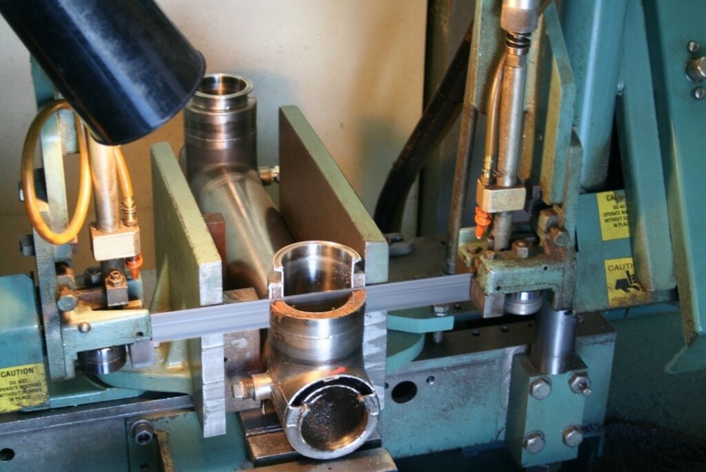
Figure 5 – Saw cut of pipe section
The circled area in Figure 6 is the same area shown in the mirror in Figure 4 and is enlarged in Figure 7. What made this particular inspection unique was the pleasant smell of chocolate during the saw-cutting of the pipe.

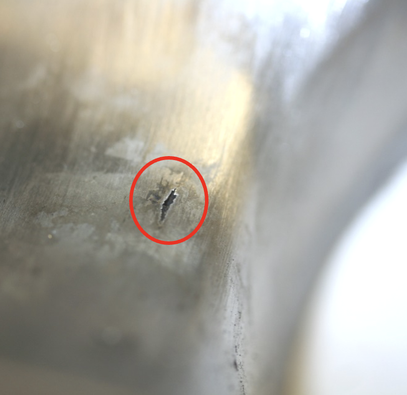
Figures 6 and 7 – Location of leak
Further disassembly occurred when the inner and outer stainless-steel sections were separated as shown in Figure 8.
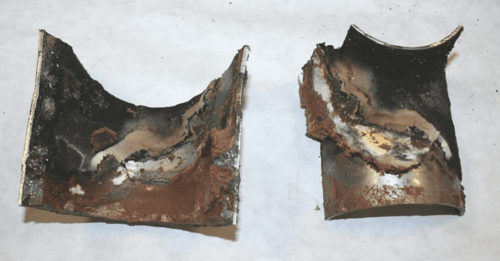
Figure 8 – Sections shown in Figure 7 separated
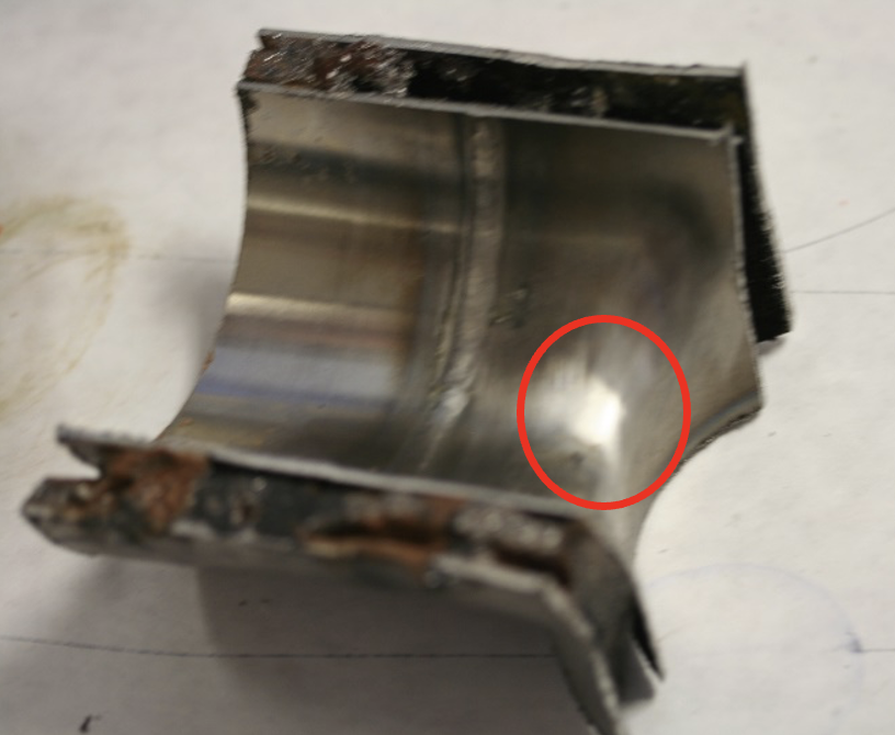
The piece on the right side of Figure 8 was cleaned and is shown in Figures 9 and 10.
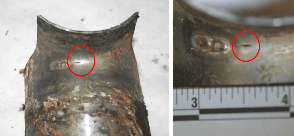
Figures 9 and 10 – Location and scale of leak. Patch weld made by tee manufacturer is left of the leak.
Cleaning also revealed the presence of a patch weld on the tee. This patch was present on the tee when it first arrived at the pipe vendor.
Engineering Inspection
The pipe was subjected to SEM analysis. (Figure 11)
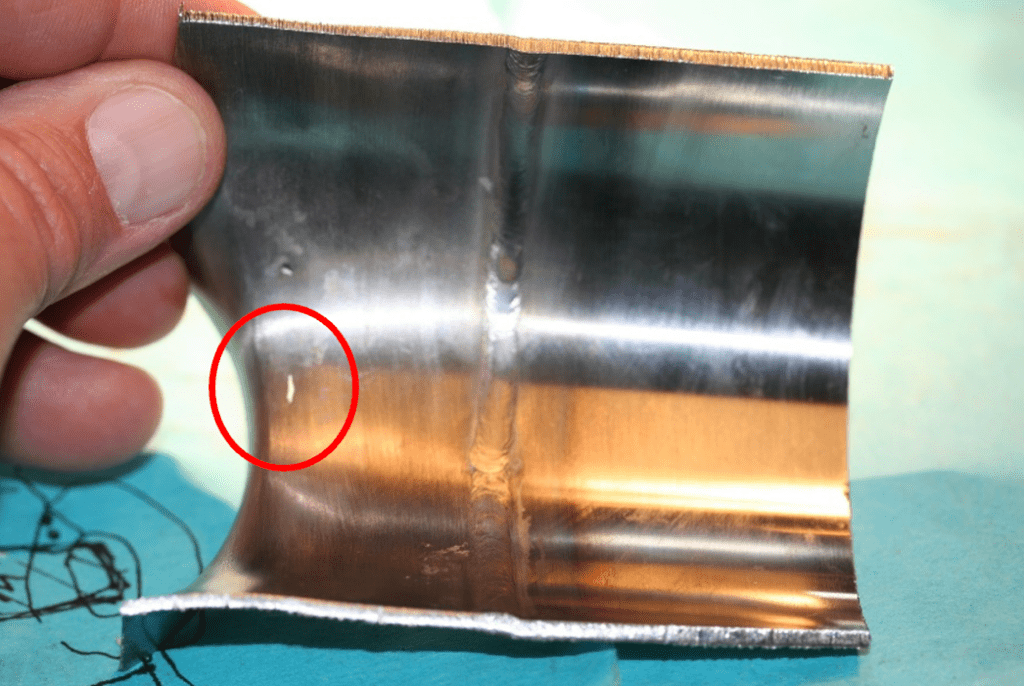
Figure 11 – Cleaned piece of pipe. Leak point denoted by arrow.
Note the location and size of the leak on the left side of the piece indicated by the arrow. The area around the leak was cut out and removed as shown in Figure 12 for SEM analysis.
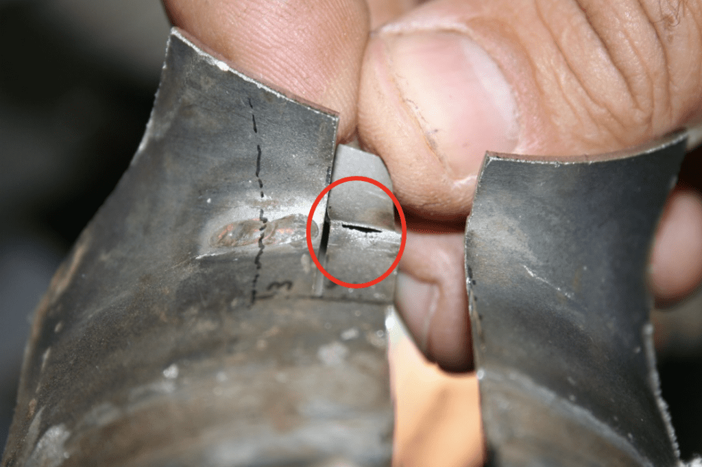
Figure 12 – Sample removed from piece.
The sample being grasped and denoted by the arrow in Figure 12 is shown in Figures 13 and 14.
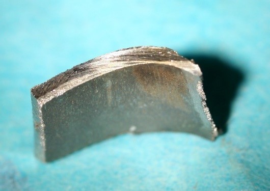
Figures 13 and 14 – Section of tee adjacent to leak
Analysis
Engineering Report
AKE is in general agreement with the explanation of the two predominant factors that led to the high stress level with the part that caused the leak: 1) thinning of the stainless-steel from grinding and polishing the patch weld, and 2) the morphological change in the stainless-steel contributed by the patch weld, causing the crack initiation in the heat-affected zone proximate to the patch weld. AKE’s findings cite the treated water in the pipe system as a contributing factor to the stress corrosion cracking experienced in the area affected by the patch weld.
AKE is not in agreement that this failure was caused by: (1) The pipe vendor’s lack of performing work in accordance with ASTM specifications, (2) lack of passivation and that it was their responsibility to passivate the pipe assembly.
Information Provided by Third Party
The water that flowed through the pipe that failed was part of the plant water system treated by the chocolate manufacturer. The chemicals that were to be used in the system were originally specified by a water treatment company. Documents provided by this third party indicated they were critical of the chocolate company’s ability to sustain the treatment plant. This is consistent with the lab report that the water may have been a contributing factor of the failure. Without further information provided, it cannot be ruled out that the lack of proper water treatment exacerbated the failure of the tee fitting.
Additionally, laboratory examination and information provided by the chocolate company indicated there was intermixing of the plant water and chocolate, described as “red water.” It raises the question of why this was not seen circulating in the water system prior to being discovered in the chocolate. According to the third party, the water returning after circulating in the pipe system was dumped into a surge tank and mixed with city water. Proper oversight may have identified the “red water” before the contamination had progressed so far and limited the amount of chocolate that eventually was claimed as a loss.
Summary
- The tee fitting supplied from the plumbing parts manufacturer arrived at the pipe vendor already structurally compromised.
- It is highly unlikely that visual cues existed in the damaged area on the tee that would have alerted the vendor to the tee’s condition.
- The tee was incorporated into the piping system, built in accordance with the chocolate company’s specifications.
- The chocolate company did not specify that the system be built in accordance with ASTM standards nor did they direct them to passivate the system.
- The vendor voluntarily subjected each pipe assembly to a pressure of 80 psi to check for leaks – four times the actual working pressure that the pipe experienced in service.
- The system was in service for almost two years before the damaged tee fitting failed.
- The chocolate company may have been complicit in the failure of the tee by not properly maintaining the water system.